Wiring for DCC has always been a complex subject especially if one requires automatic operations and signaling as well. I carefully planned the DCC installation for Abendstern, breaking it into bite sized chunks so that installation and future troubleshooting would both be easy to do…
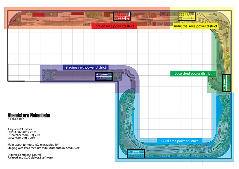
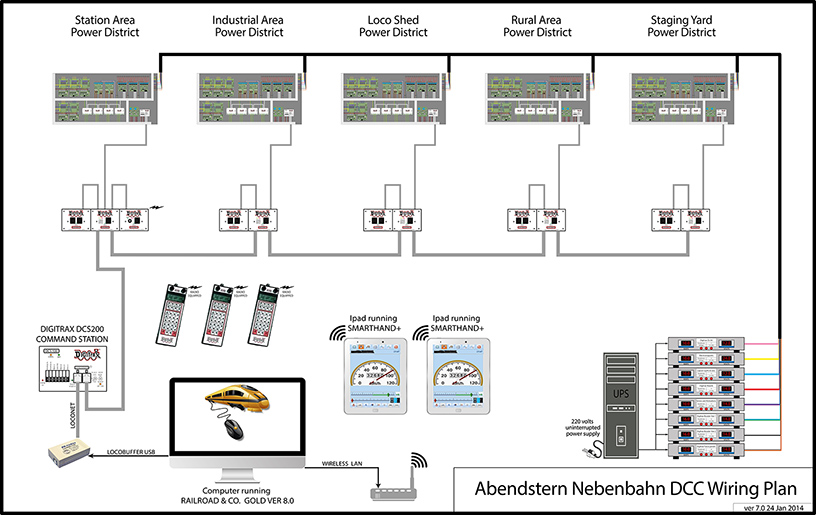
I decided to divide the layout into five power districts – Station area, industrial area, loco shed, rural area and staging yard. The components required for each power district was installed onto a panel, which was then located in a central location of that power district, as depicted by a rectangle in the below illustration.
 click on pic
 click on pic
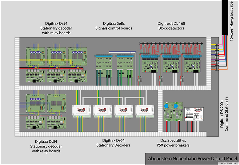
A panel would hold an 8 amps booster & circuit breakers as well as all the necessary block detectors and stationary decoders required for that power district. This would make troubleshooting and isolating problems simpler as well as arrange the entire wiring in a logical manner…
 click on pic
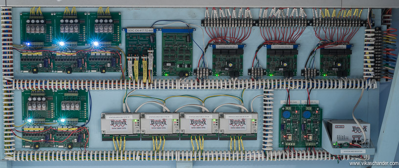
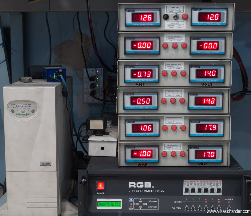
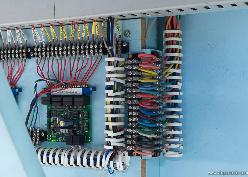
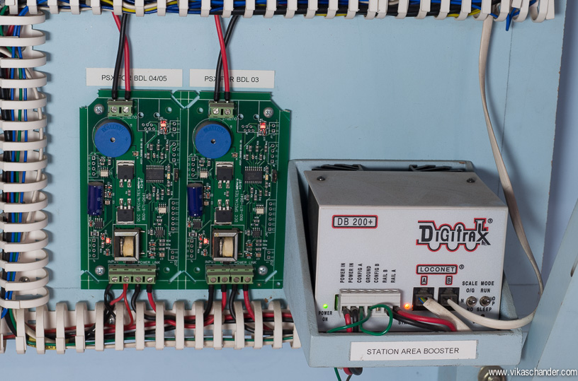
Below is an actual power district installed below the layout…
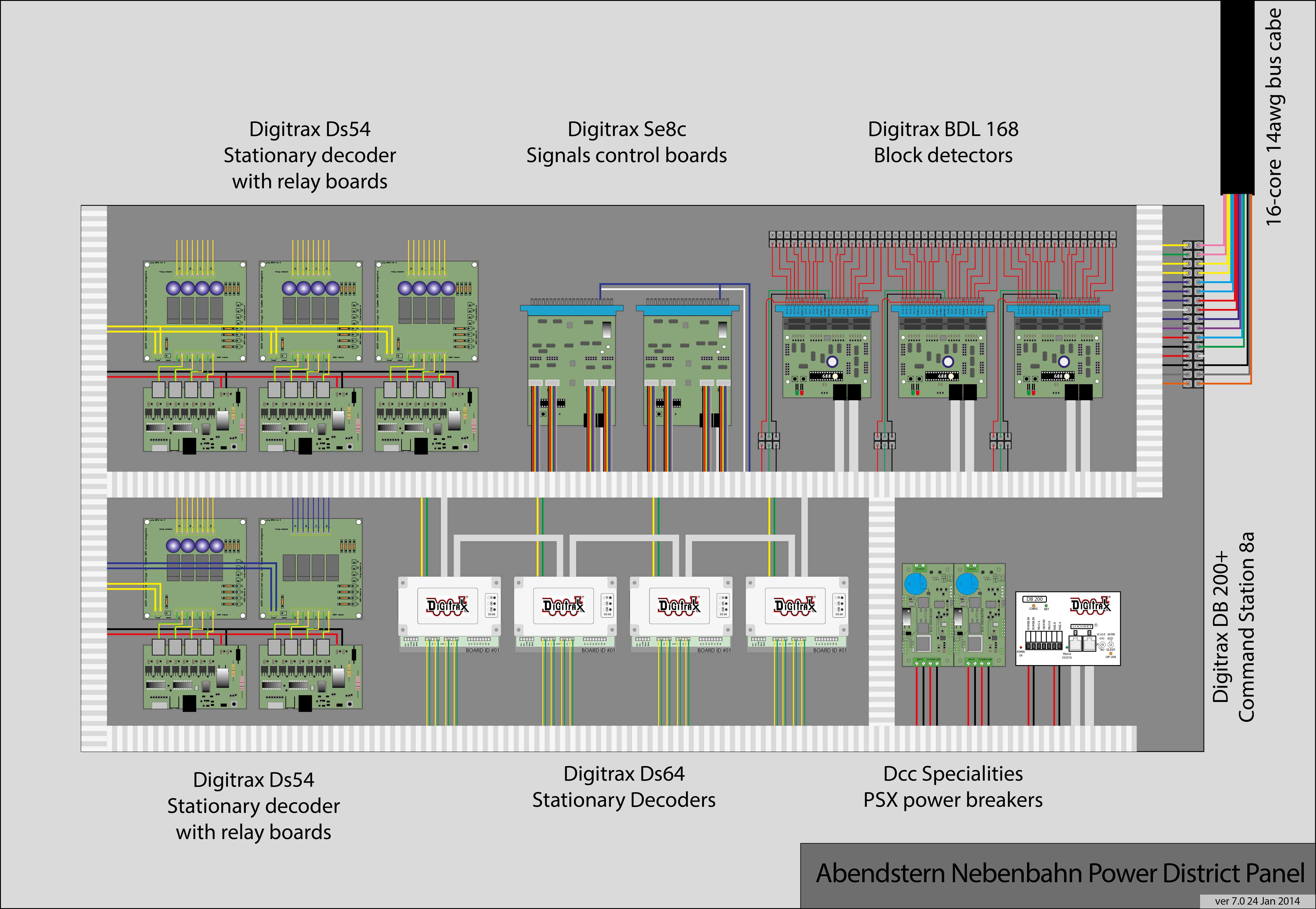
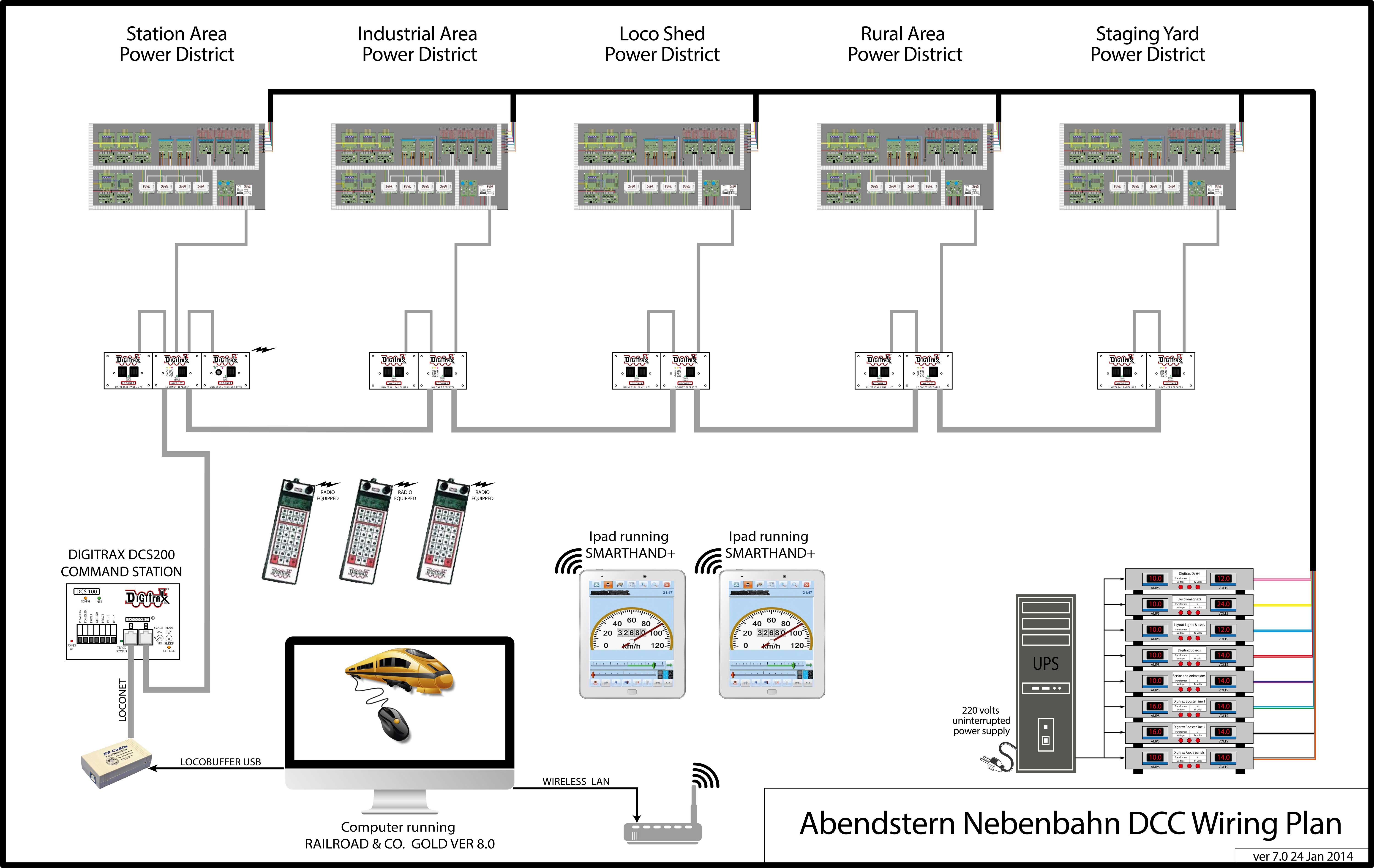
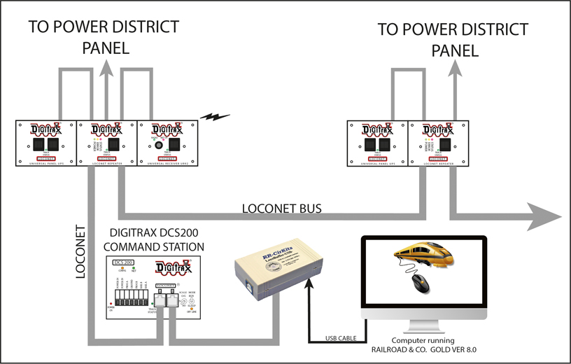
Here is a wiring schematic for a clearer understanding of the complete setup.
 click on pic
 click on pic
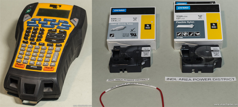
I used a Rhino Labeller to print out labels and heat shrink tubing so that everything could be neatly labeled for easy identification and trouble shooting …
I set up a central location for the power supply, which consisted of seven voltage transformers supplying various voltages. The transformers are connected to an Uninterruptible Power Supply as there are a lot of power outages here in India and these outages can play havoc when the layout is running under computer control.
A 16-core cable with each core consisting of a 14 AWG wire was used as a bus wire from the transformers and was daisy-chained to supply all five power district panels…
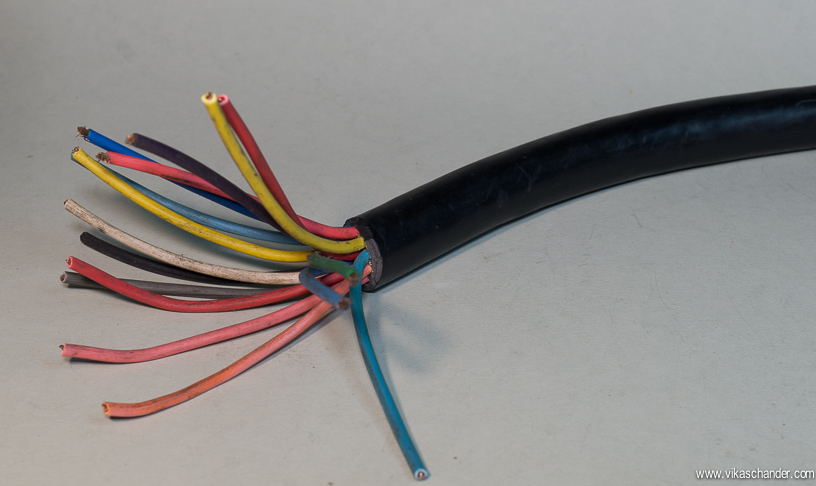
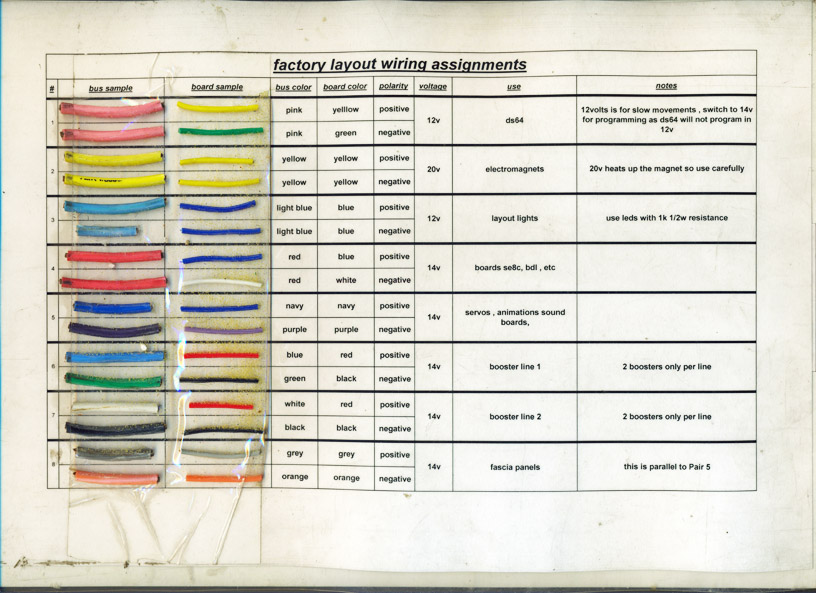
I made a reference card, which at a glance showed me the color-coding and wire type of the 8 different circuits of the bus wire. The card also shows the color-coding and wire type used within the power district panel and beyond.
 click on pic
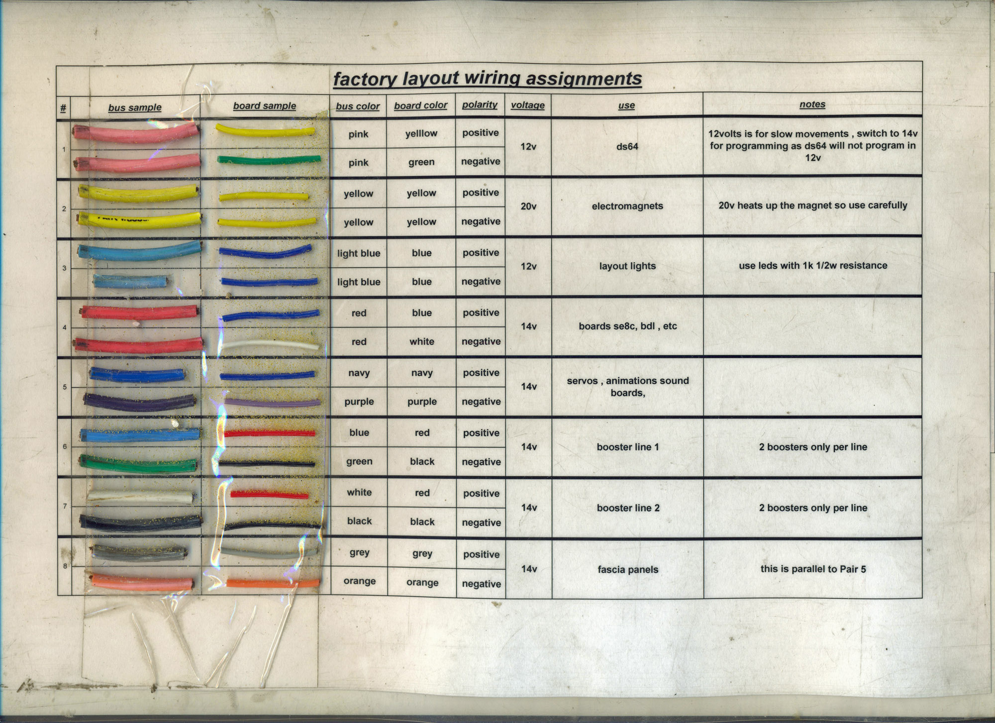
In hindsight, I would have liked to use matching colors for the wires in the bus cable and those within and downstream of the power district panel but unfortunately I used what was easily available to me at that point in time…
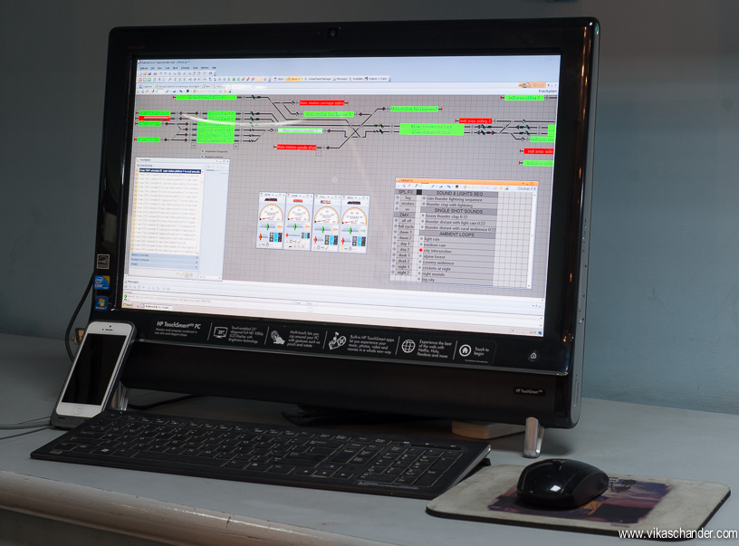
A PC running Freiwald Software’s TrainController Gold controls the layout.
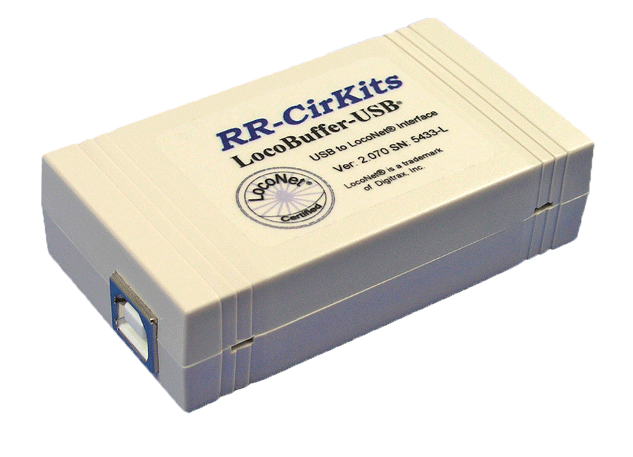
A LocoBuffer USB takes the signals from the computer and converts it to a Loconet signal, which is the protocol, used by Digitrax.
A loconet bus was setup using a Digitrax DCS 200 command station and five Loconet repeaters. Each of the five power districts is fed with a protected signal coming off, of the Loconet repeaters. This meant that if there is a problem related to the Loconet signal in a particular power district, that power district would be isolated while the rest would continue to function normally.
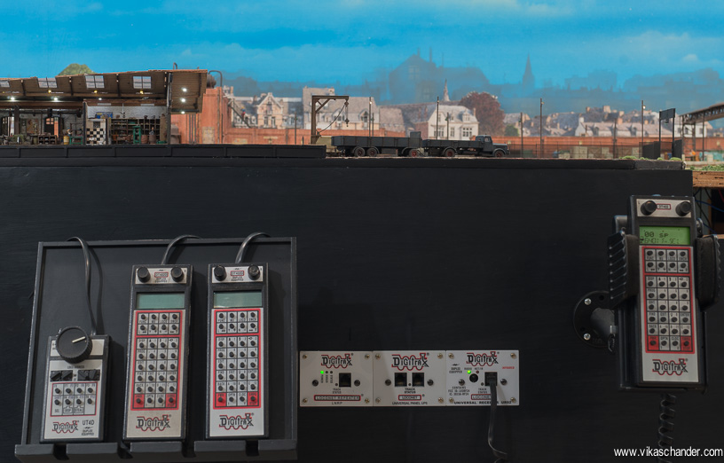
The Loconet repeater along with Up-5 and Ur92 radio panels, are installed on the fascia in front of each of the power district panels. Indicators on the Loconet Repeater panel make it very easy to identify the power district with the problem.
Each power district panel has a Digitrax DB 200, 8amps booster. The track power from the booster feeds into two (or more) PSX circuit breakers from DCC Specialties. This makes it possible for dividing a power district into two (or more) further isolated zones and prevents shorts in one zone from shutting down the entire power district. A speaker on the circuit breaker provides audio feedback in the event of a short circuit.
For automatic computer controlled operations, motorized turnouts operable with DCC switch commands are essential. In an earlier layout I was using solenoid motors to switch the turnouts but I found them extremely unreliable resulting in quite a few misfires resulting in trains ending on tracks different from where they were intended to go. I have since switched to Tortoise stall motors to switch the turnouts and have found them to be extremely reliable so much so as to eliminate the need for installing a turnout position feedback mechanism. The Digitrax DS64s were setup for the Tortoise switch machines. Command signals would be provided by loconet and not track power. Thus in the case of a short due to a loco running onto an incorrectly thrown turnout, the DS64 could still be able to receive commands and one could correct the situation.

Installing the Tortoises from beneath is a tedious process and can result in incorrectly aligned turnout throw rods. I have developed a method to install the Tortoises as can be seen in this post. Further, the German prototype railways calls for a point lantern to be installed next to the turnout showing the direction the turnout is thrown.
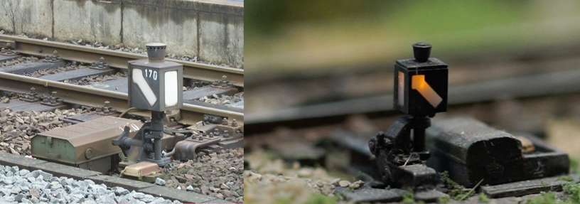
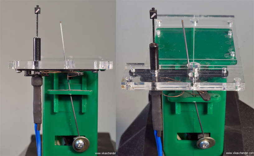
Weinert makes a point lantern kit for this purpose. This is a tricky kit to install and animate, especially when working from below the layout. I designed a small laser cut acrylic plate to which I can mount the Tortoise as well as the Weinert point lantern on my workbench.
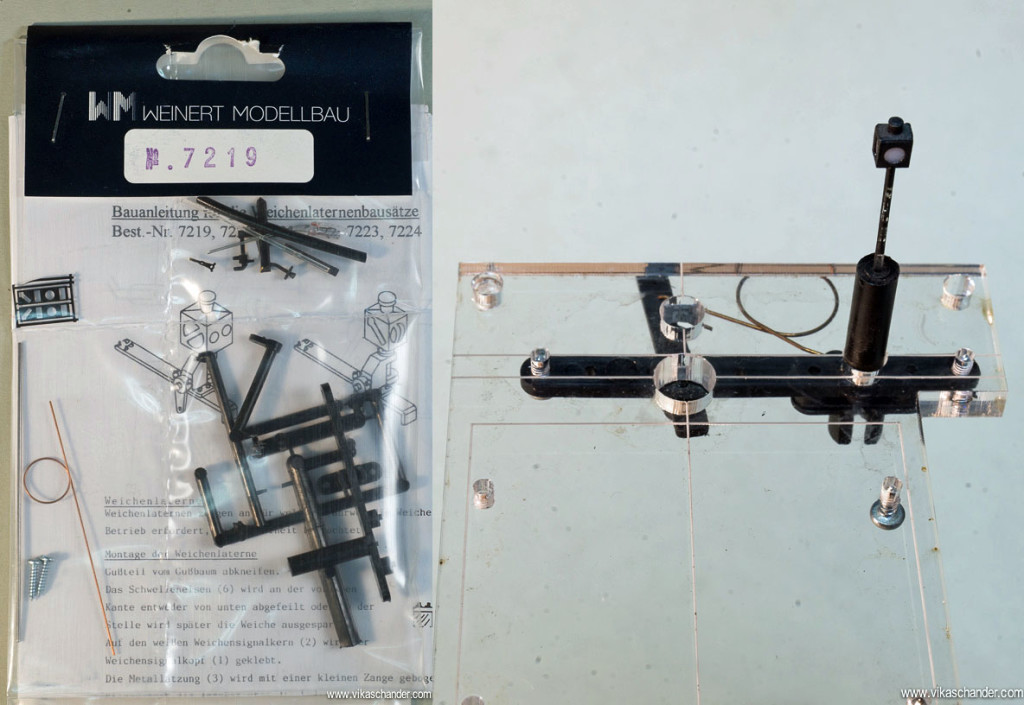
With this system not only is it easy to mount the Tortoises, the Weinert point lanterns also work very reliably with no tweaking required post installation…
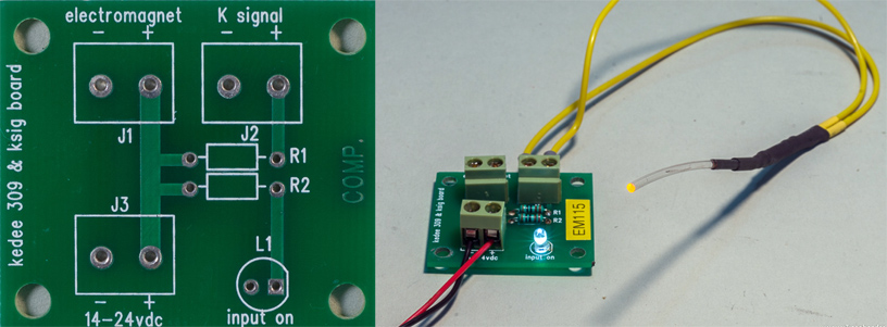
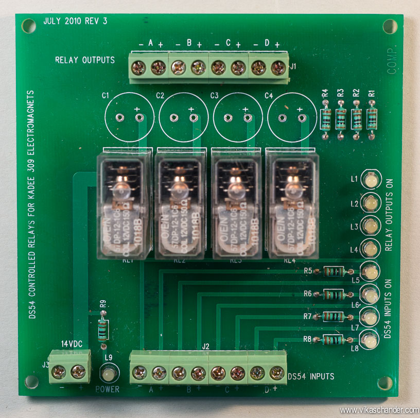
Electromagnetic uncouplers are triggered thru relays fired by DS54s, so that higher currents could be handled. This would otherwise not be possible using the direct outputs of the DS54s, which are rated at about 500ma continuous. Therefore, it is now possible to assign a DCC switch address to each electromagnet and the electromagnets could be fired using switch commands from the throttle or from TC Gold. I setup the output of the DS54 to automatically switch off after 10 seconds, thus eliminating the risk of coil burnout on the electromagnet. If one is unable to complete the uncoupling process in 10 seconds, it is possible to re-trigger the output thus increasing the hold time of the electromagnet by further 10 second increments.
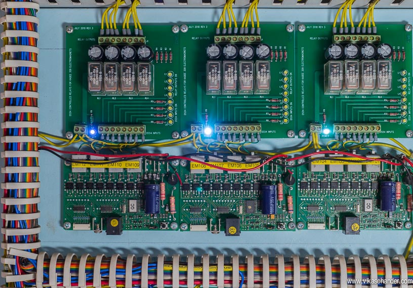
I designed a small PCB to mount all the relays & components and keep the wiring neat and clean.
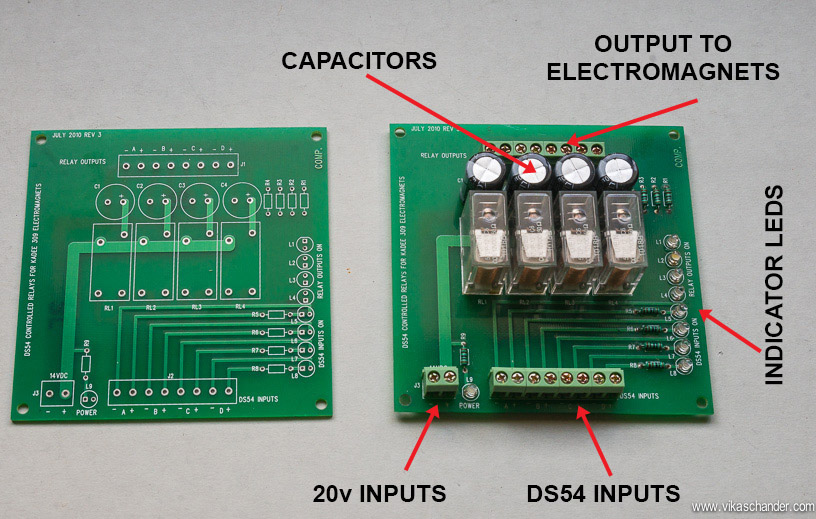
I also rigged up another daughter PCB to which I could connect the electromagnets as well as a fiber optic tube. The fiber optic tube would give visual feedback of the electromagnets location and operation. In dark operating conditions this is a godsend.
Here’s a GIF animation showing the fiber optic marker of the electromagnet in operation.
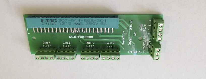
![]() For track or block detection, I use the Digitrax BDL168s. These have been hardwired/soldered to the sandwich connector and then onto a terminal block…
For track or block detection, I use the Digitrax BDL168s. These have been hardwired/soldered to the sandwich connector and then onto a terminal block…

Subsequently, I came across the BDL 168 terminal block wiring adapter which makes the job of hooking up the BDL 168s easier and I will use these in future installs.
The Digitrax se8c signal stationary decoder is used to control the shunting signals only.
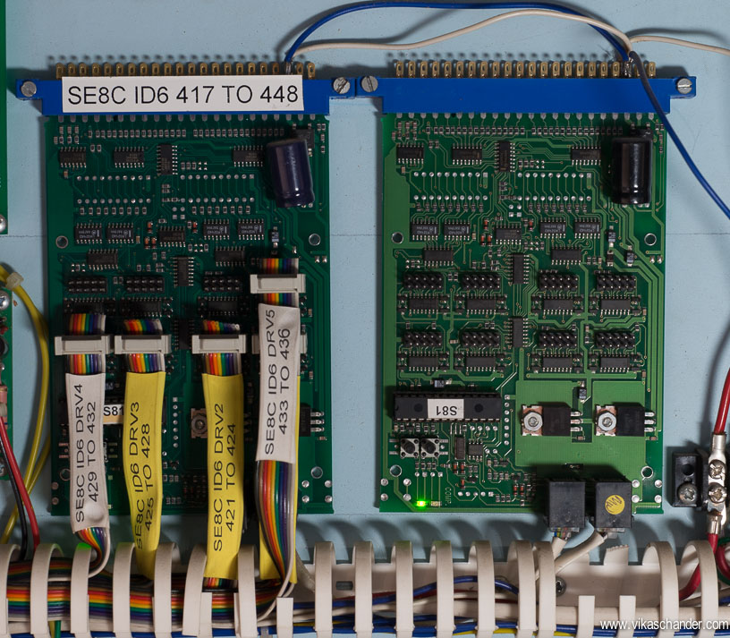
These signals are relatively easier to control and program as they are simple two aspect signals.
The main signals are however a complicated affair, with some signals showing as many as 14 or 16 aspects. These signals are controlled by the LDT DB-DEC signal decoder which are installed downstream of the power district panel and closer to the actual location of the signal on the layout.
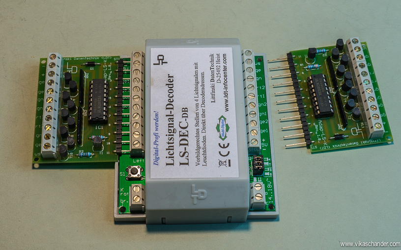
The signals I am using are from NMW and these are common cathode signals. The LDT signal decoder is equipped to handle them along with providing the necessary aspects of prototype German railway signaling practices. Below is an exit or Ausfahrsignal from NMW showing 14 aspects………
The on-layout lighting of structures and such is also controlled via DCC switch commands. For the heavier load circuits such as yard and platform lights or point lanterns a Digitrax DS54 stationary decoder is used to control the relays on a board similar to the one which I use for the electromagnets., sans the capacitors.

For lighting up the structures, streetlights, vehicles and other less demanding loads, I use the 16-output Q-decoder Z1-16. The Q-Decoder Z1-16 is highly programmable and has many effect options such as fluorescent lights, gas lamps, welding lights etc. To make wiring easier I designed a PCB for mounting on two Q-decoder Z1-16s along with a DCC track signal booster so that precious DCC current is not robbed of the Digitrax Booster.
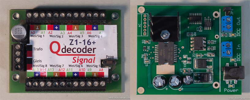
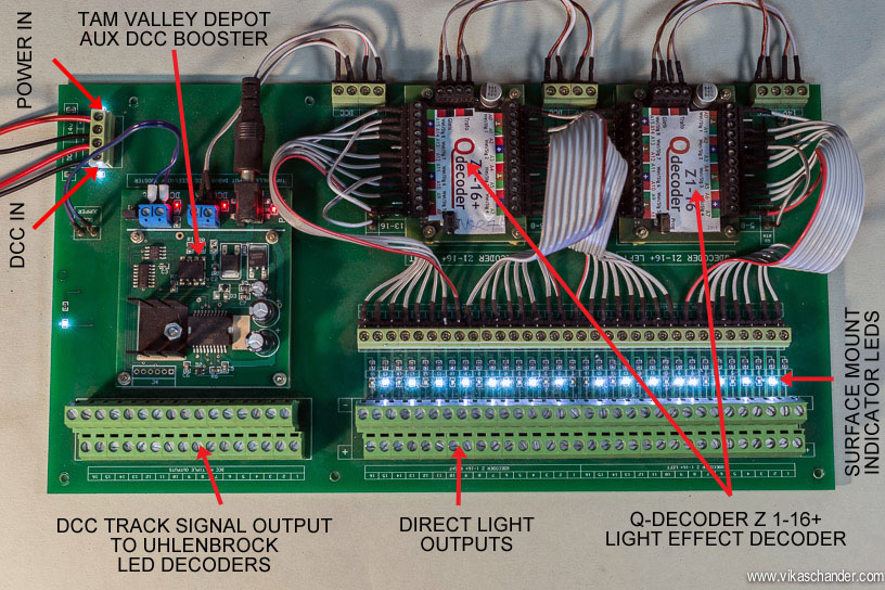
I installed SMD LEDS and resistances on each of the outputs of the Q-decoder and this allows me to program and review the behavior of each of the outputs of the Q-deocder prior to the connection of any lamps to the outputs. A great time saver especially if one is programming on the workbench and does not want the clutter of the wires of many lamps and lights.
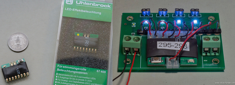
Whilst, the Q-decoder is used to handle mainly incandescent lamps, for controlling LEDs I use the 4 output Uhlenbrock led decoder. Their small size also allows for installation inside buildings and structures creating what i like to call DCC structures !!! I made a smaller PCB for the Uhlenbrock LED decoder and these are mounted remotely and closer to the fixtures it is meant to feed….
All in all, wiring up these power districts was easy to do and the logical layout, clean wiring and the labeling all combine together to make trouble shooting a breeze though not much of that has been needed since the three years this has been in place.
Dear Mr. Chander
A number of sources including DCCconcepts in Australia stated that the red and black DCC power bus wires must be twisted together about 12 turns per meter to lower inductance. DCCconcepts even sells such twisted bus wire.
But thank you for your quick response.
Well , i use simple straight cables…. i am not sure what u meant by twisted bus cables …..vikas
Dear Mr Chander
Is it necessary to use twisted DCC bus cable? Are you using twisted DCC bus cables on your Abendstern layout?
I’m sure it does! Please continue to post. Your blog gives encouragement and enjoyment to so many.
Best regards,
R
Hi rob
Actually i have hardly done any maintenance on the couplers or the uncouplers. they have worked very well over the years. For computer control the main challenge is to have the trains and layout working reliably otherwise everything goes south very quickly …
cheers
vikas
Vikas,
I read the posts about Abendstern and didn’t get as far as your modules pages! Thanks for being patient.
I have used the 309s on a small exhibition layout with reasonable success. Do you find them reliable if the couplers are well maintained? Any tweaks required to work reliably for computer control?
I love the rigorous and considered approach that you have taken in building this very entertaining railway.
Best regards,
R.
Hi Rob,
Well i did not install the electromagnets exactly as per the manufacturers instructions!!
You could read about it here – Kadee 309 install
Vikas,
Lovely work. What electromagnets did you use? Did you install them strictly as per the manufacturer’s instructions?
Hi Anthony.
The reason i use a dedicated command station separately and not use it as a booster is because in case there is a short circuit or circuit breaker failure in a district using a command station as a booster, then all the power districts would stop receiving Loconet commands and the layout would be compromised.
in my current setup a booster short circuit/failure would only shut down that district while the others would still be functioning and receiving Loconet commands from the command station
i do however use the track outputs of the command station to test locos etc on my workbench along with its programming track so the command station is not entirely wasted !!
cheers
vikas
An inspiring layout with some really useful tips and guidance for my forthcoming layout. I do, however have one query and would be extremely grateful if you could help. Why did you decide to use the Command Station as a stand alone unit that did not power any track, instead of using it to replace one of the five boosters in the power districts?
Many thanks,
Anthony
Fantastic setup. I really like the animated turnout lanterns.
great work !
Excelent presentation and ideas for my layout, especially about the lantern turnout.
Another fantastic presentation and explanation of your wiring, their components type, brand and locations. Your panels look extremely professional and are as much a work of art as your layout! I too will try to adopt your principles, processes and some of your ideas on my layout American layout here in Australia. Keep up the excellent work and ideas flowing.
One word – Genius
Another fantastic post, Vikas. This will be useful to me for many years down the line! 🙂