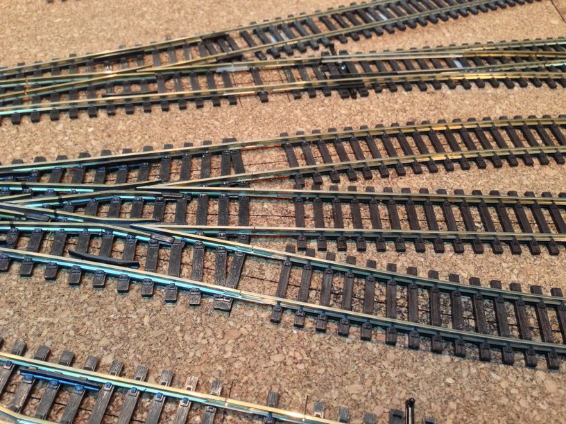
Now that the points were installed , we come to probably the trickiest part of the whole FREMO staging yard build………How do we get the track across the module joints ? Maintaining horizontal and vertical alignment was key. One also needed to ensure the track did not move or rip out during the erection/dismantling phases……..
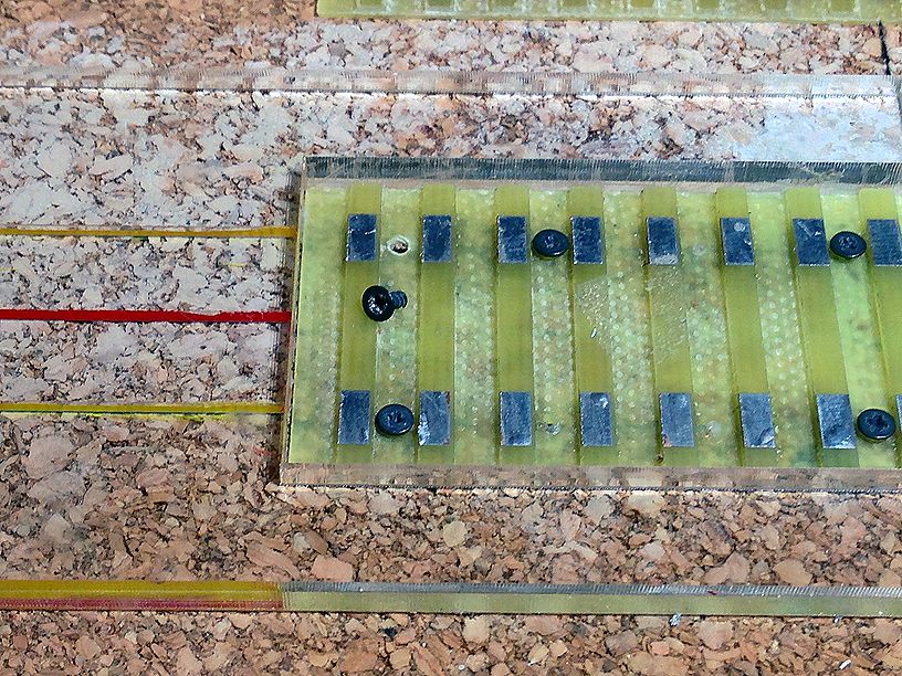
Over the years i have seen two different methods , one being the rail soldered to a set of screws at the module edge and the other being the track soldered to PCBs which in turn are glued/screwed on to the modules edge …
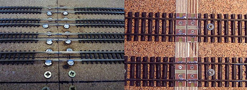
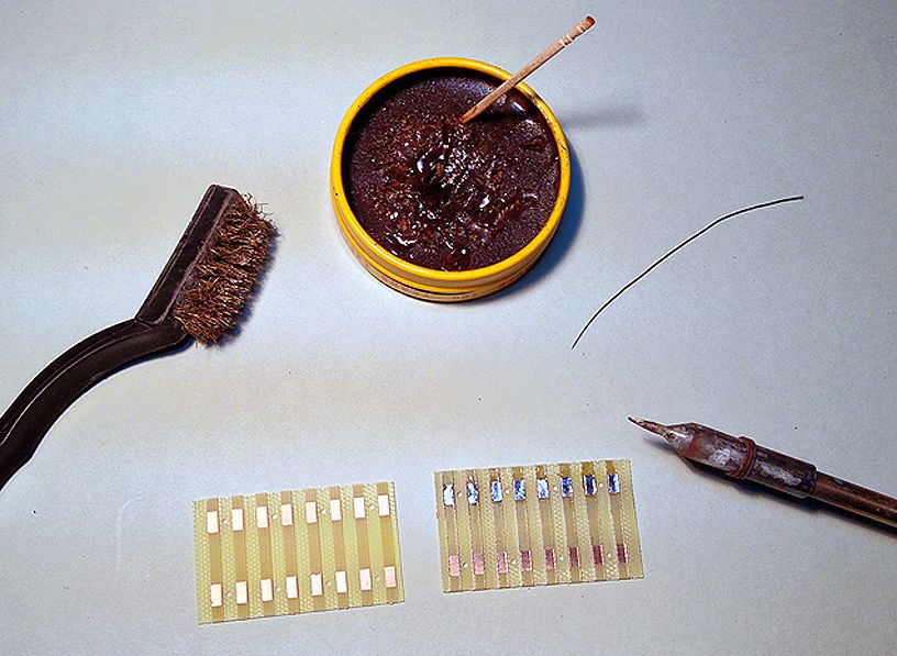
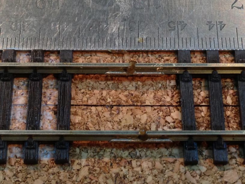
while both methods work and serve their purposes, one can see form the above it is not exactly a very neat solution .Enter BNM hobbies and their products targeted specially for this job , the various avatars of the end tie plates …..
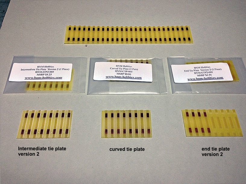
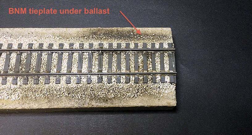
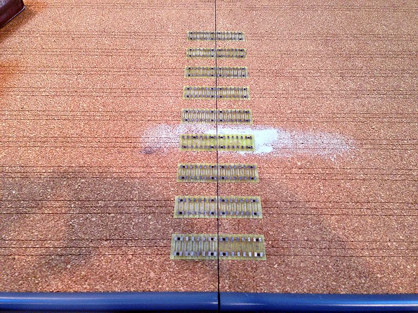
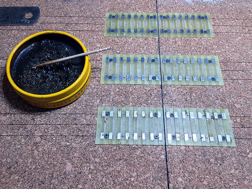
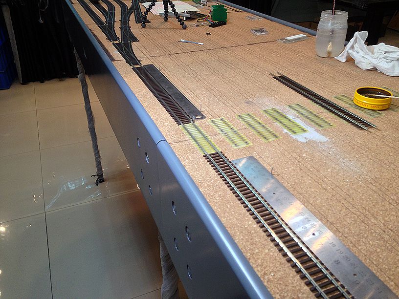
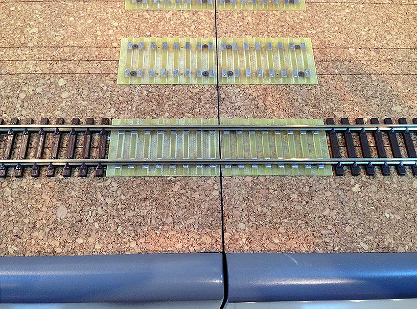
These are basically printed circuit boards with the copper/nickle silver CNCed away leaving just the rectangles to which the track can be soldered. BNM hobbies offer them in 4 types and i chose to use the Intermediate Tie plate version 2 ………when ballasted they do look neat and nice ………. so nice that one can’t see them as they disappear totally !!!
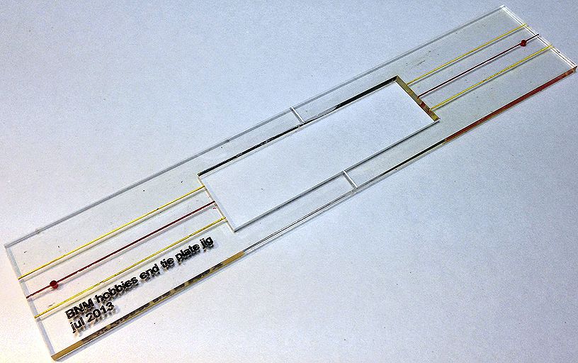
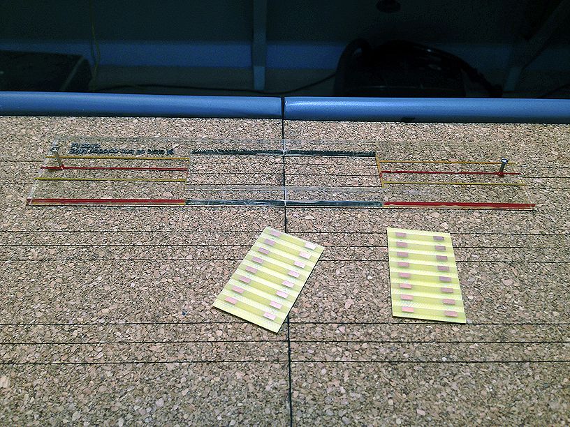
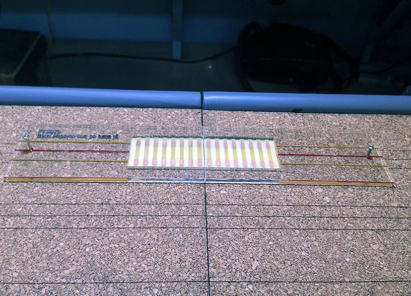
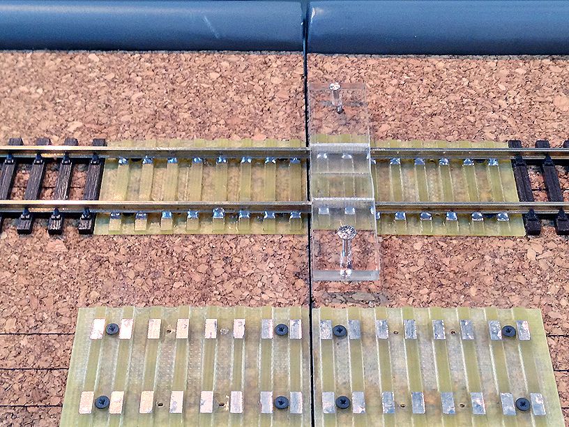
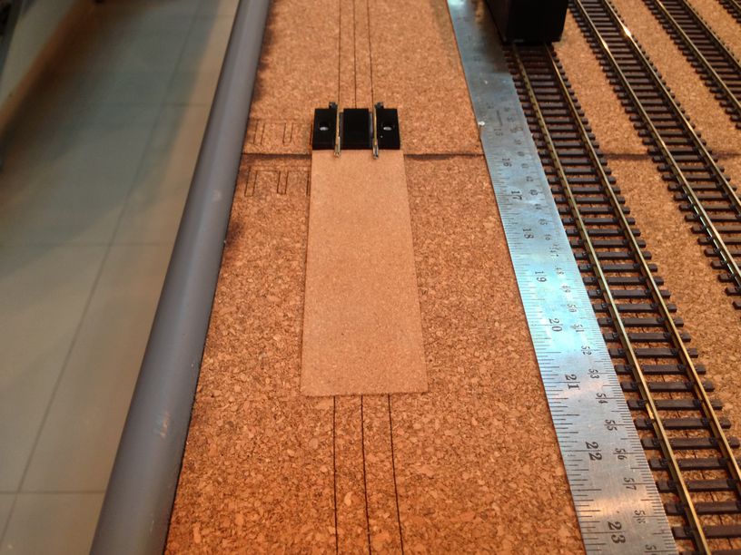
I conjured up a jig which would speed up the installation and make it more accurate as well , taking advantage of the already laser engraved cork with the track centerlines and rail lines , I engrave them into the jig, later coloring the centerline as red and the tracklines as yellow. I also engrave in an additional line, colored in white, marking the center of the jig and this will be aligned to the joint line of the modules …….
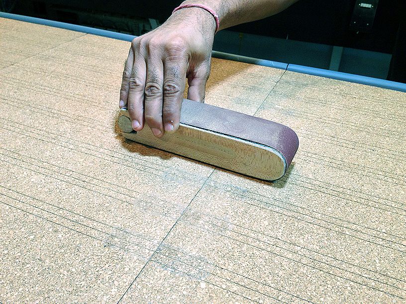
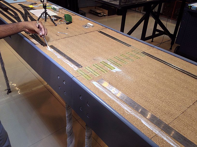
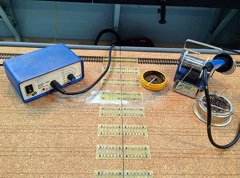
i also presoldered/tinned the tie plates prior to installing them …… and then i lightly sanded down the area around the module joints with a sanding block loaded with 320 grit sandpaper..
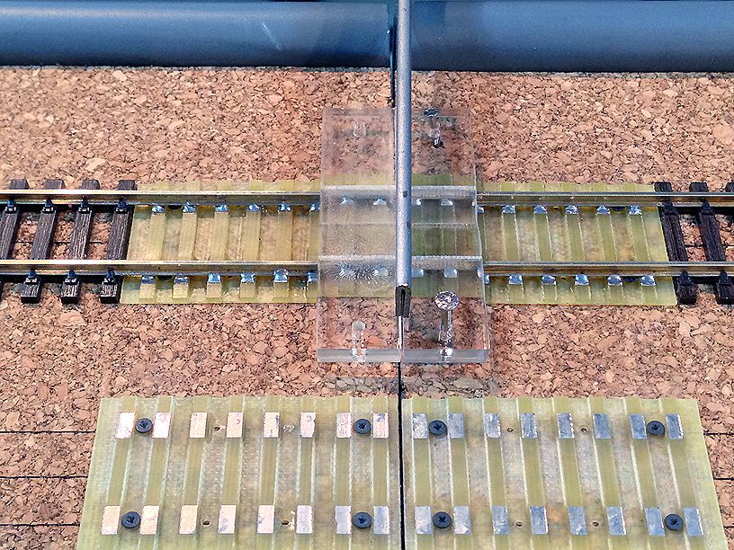
and put into place the tie plate jig , held down by two pins ….. all the while ensuring the red centerline , the yellow railines and the white joint line align correctly…..
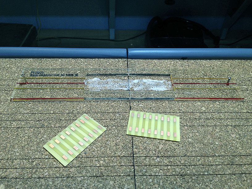
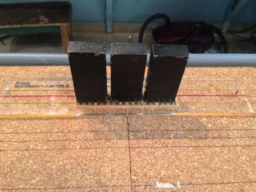
i then put in some white glue and put the tie plates into the jig and weigh them down till dry ……
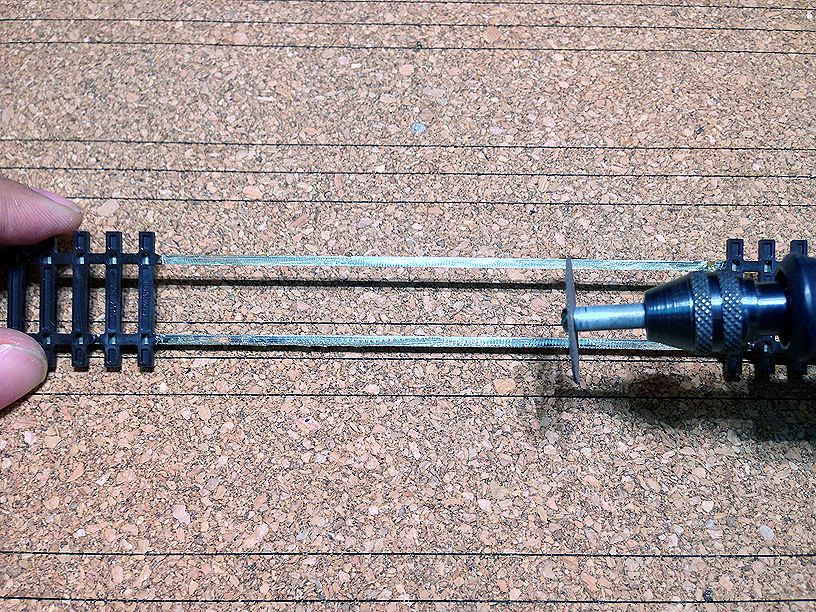
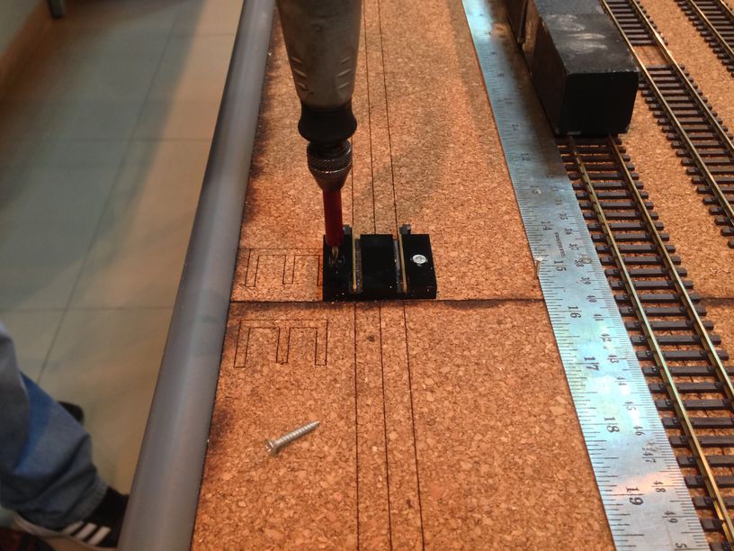
While waiting for the glue to dry i set up a Dremel rotary tool and some 15mm x 1.4mm wood screws from Fohrmann Werkzeuge, Germany …..
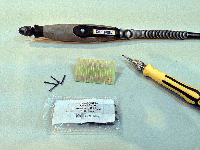
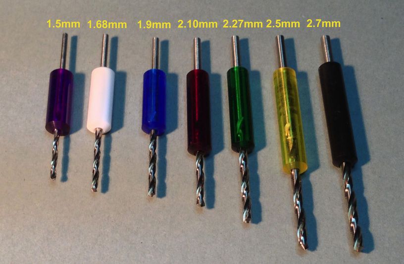
I also used a 1 mm drill bit to drill a pilot hole and a 1.9mm drill bit to ream the holes in the tie plate so the screws could pass thru. I had at hand a multi-colored collared drill bit set from Stewart MacDonald, which was mighty helpful to set the correct drill depths ………
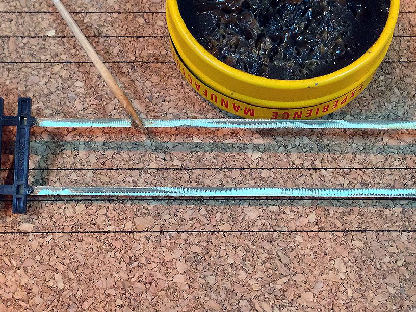
the wood screws are delicate and one needs to be careful while screwing them in or else u could break them off and then would not be able to extract the body of the screw from its hole leaving one with no choice but to put in another screw into an alternate hole …..
in my rush to put in all the plates , i made an error …..
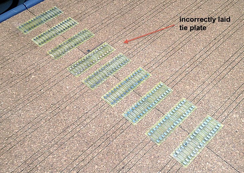
which required me to lift them off the cork which in turn left an uneven surface which then needed to be filled with humbrol and sanded down …..
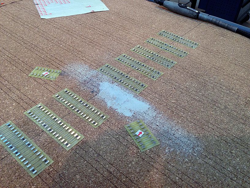
and we were back in business once again …..
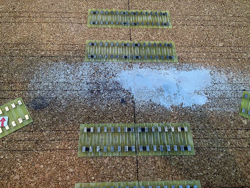
Now that all the tie plates were done i cleaned up the joints with a knife …….
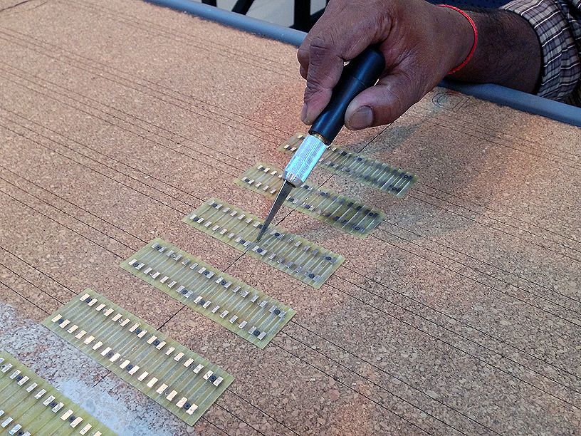
and separated the modules ……
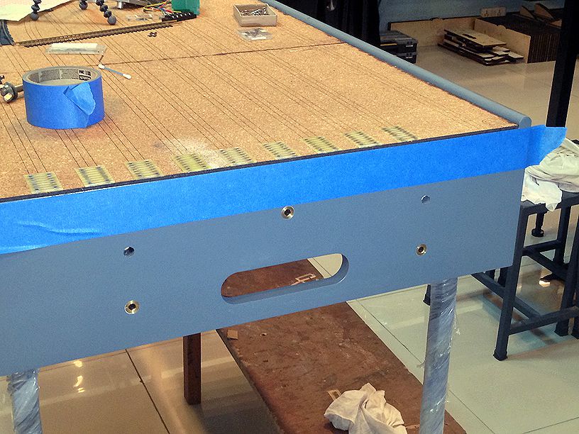
applying some masking tape so as not to damage the paint i very lightly sanded the edges to remove any glue residue and clean up the tie plates …
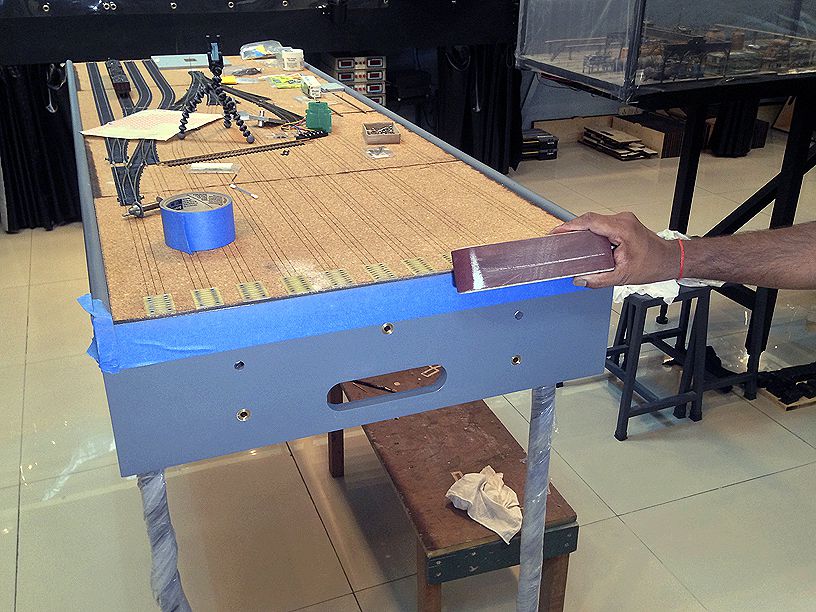
Then the modules were put back together for laying the track across the joints. I took some flextrack and cut off the ties at the appropriate location to fit over the tie plate and with a Dremel cut off disk i roughed up the underside of the rail and applied some flux in preparation for soldering it to the tie plate …..I also applied flux to the tie plates ……
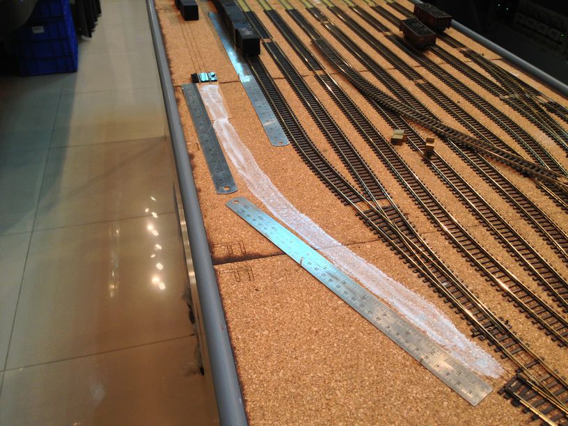
I then test fitted the track to ensure there was no issue with the levels …… the straightedges ensure that the track is laid in a straight line…
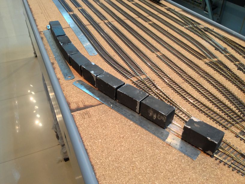
and put down the track using white glue and weights ……
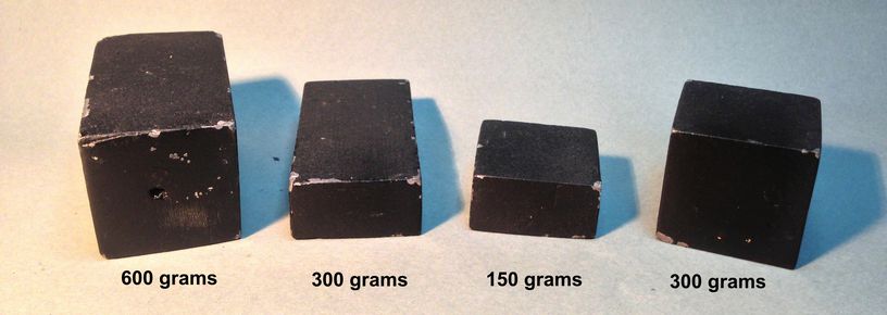
I find the weights invaluable for track installation and other works around the layout .A couple of years back i had some made in various weights and sizes and they have been very handy to have ……..
Next up , the rather enjoyable & therapeutic task of actual soldering. I used a 60/40 Tin/Lead Rosin core solder which was 0.5mm in diameter so that there is not too much solder in play and i have greater control with it. I used a variable temperature 50 watt soldering station from StarTec. I wanted to use the resistance soldering method but a few experiments showed that it tended to lift the nickle silver of the printed circuit boards so i abandoned the idea……..
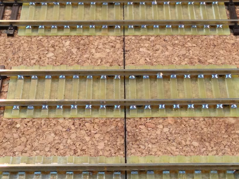
neat and clean joints were the result , i do take special pride in my soldering skills !!!
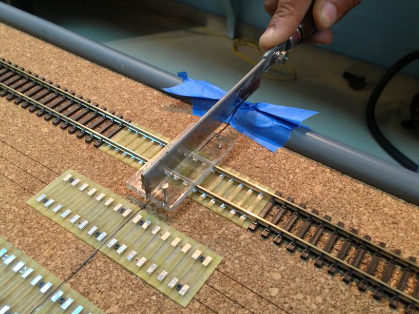
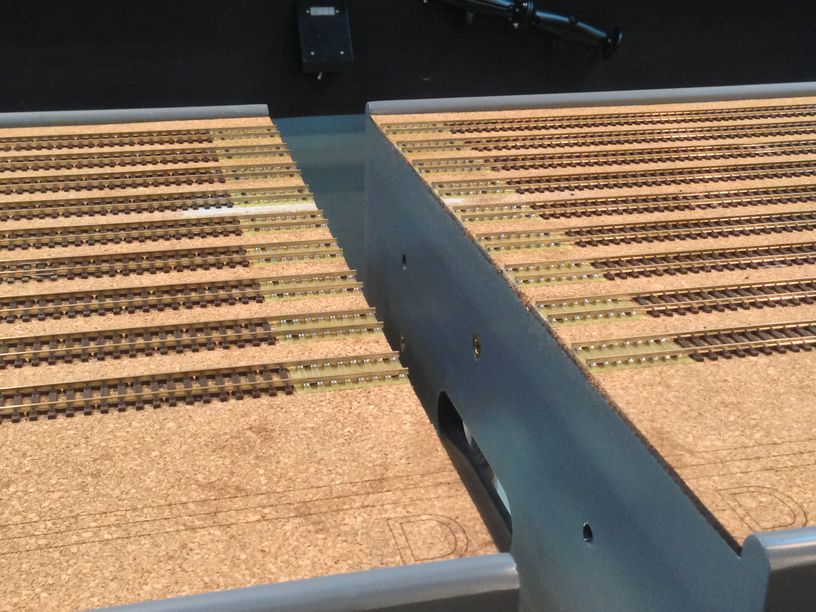
Next the tricky part of cutting the gap ………. i put a small guide jig , 90 degrees in relation to where the joint between the module was. The intention was to help keep the saw true in the vertical and horizontal planes during the cutting process so that we would not get an angled cut …
I lined up my Zona saw next to it and snugged up the other side of the guide jig …… added some masking tape to protect the sides of the module and sawed away in gay abandon …..
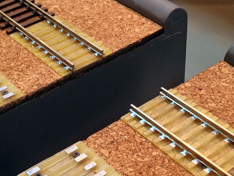
the result was a nice clean square cut …
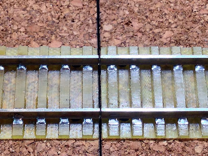
i test ran some wagons across the gap and it went smoothly …….
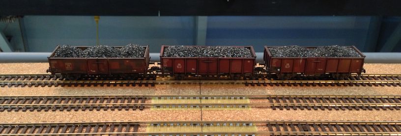
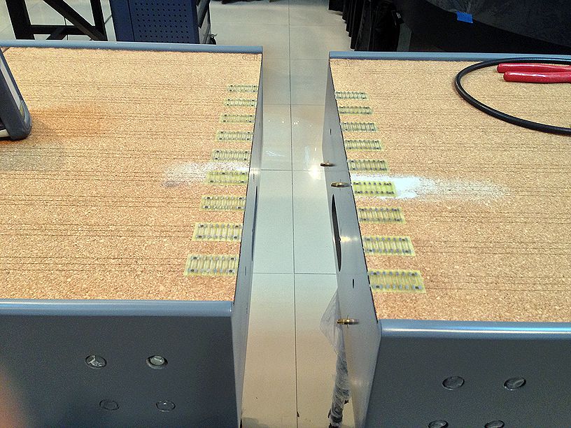
i then separated the two modules to see the result ………quite happy with it …….!!!
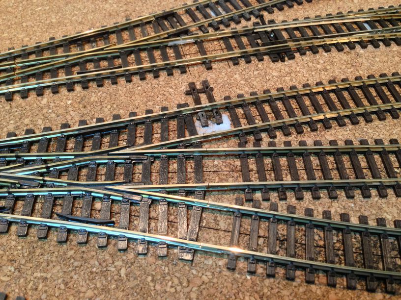
and here we have all of them done ……
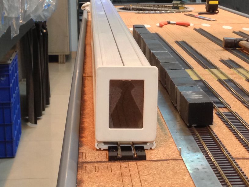
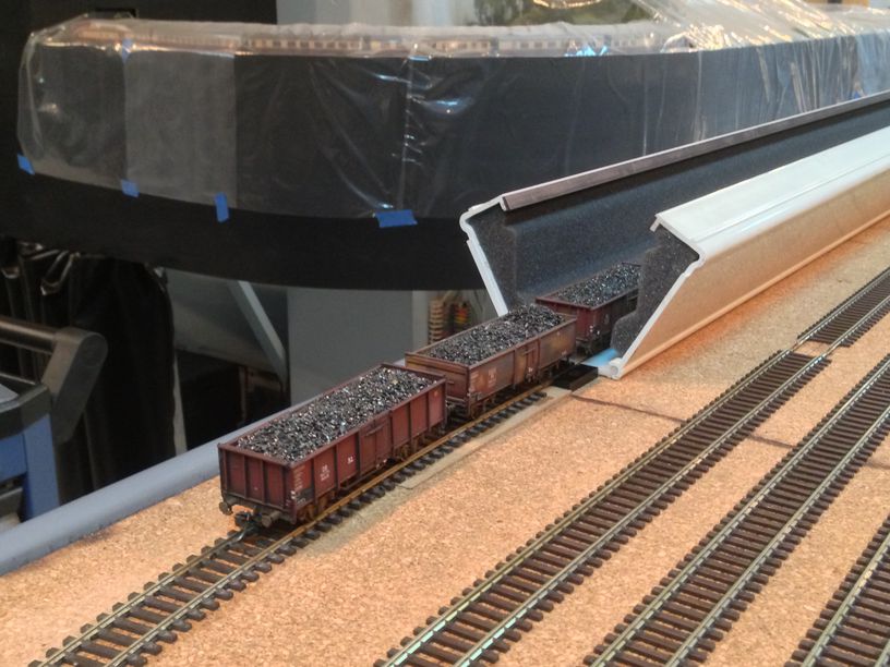
next order of business was to install the Trainsafe Cassette system. The Trainsafe cassette interfaces with the layout track thru an adapter plate……
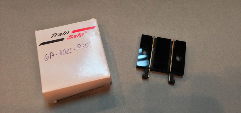
i installed the adapter plate in its designated location and test fitted the TrainSafe cassette ….
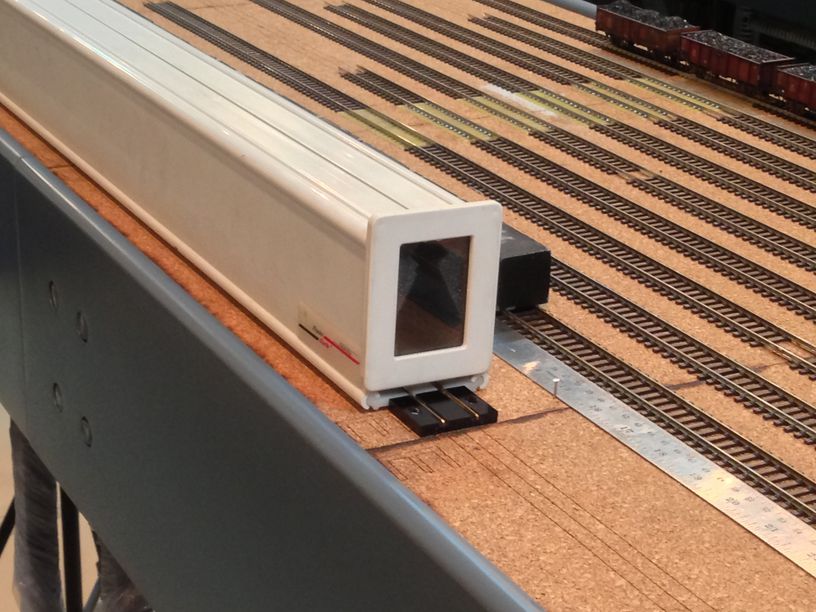
The adaptor plate is raised from the cork level so i made a small ramp for the track to climb up to the adaptor plate …..
The track in the adaptor plate is Cd75 so i had to use some Cd100 to Cd75 transition joiners …….
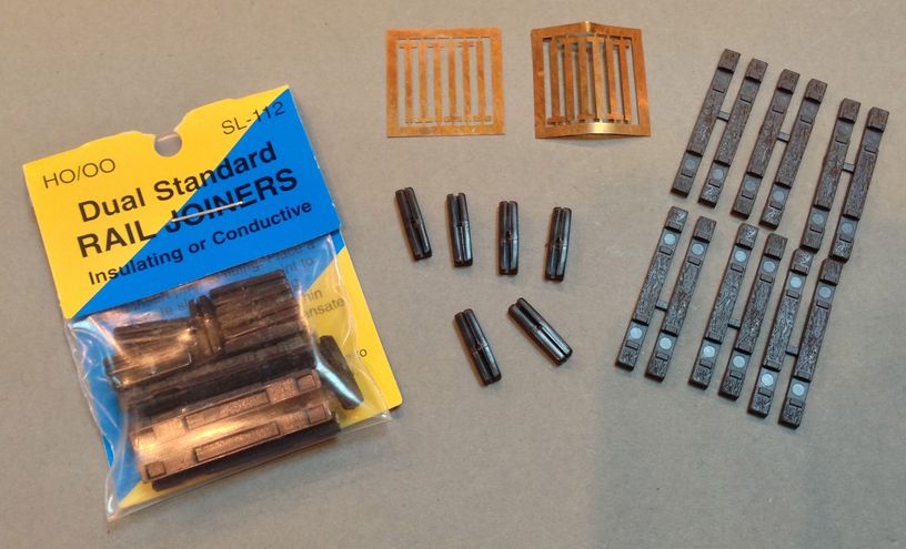
The joiners are made of plastic ,however they can be installed as current conducting by slipping in the etched brass pieces into the joiners…… I installed the frog side joiner as non conducting, keeping the stock rail side as conducting …….
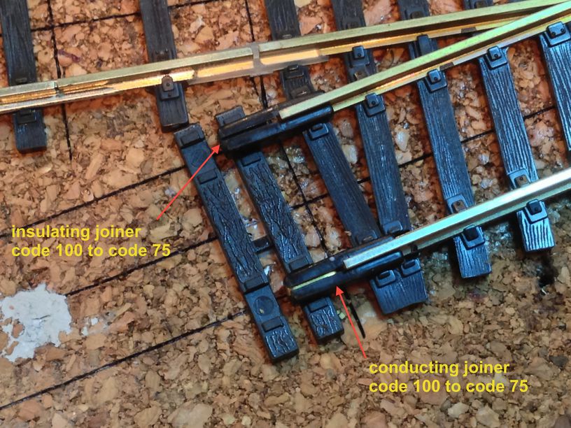
I chose to do this at the switch which leads into the Trainsafe from the yard throat rather than try to fit it into the curve between the switch and the adaptor plate as i wanted the curve to be a single piece of flextrack with no joints……
i test ran a couple of wagons to ensure all was fine and there were no bumps along the way …….
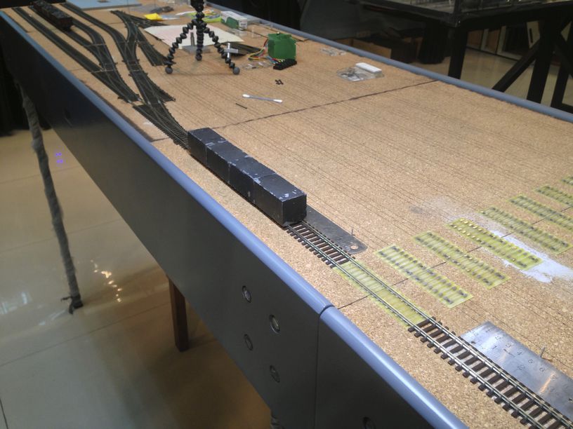
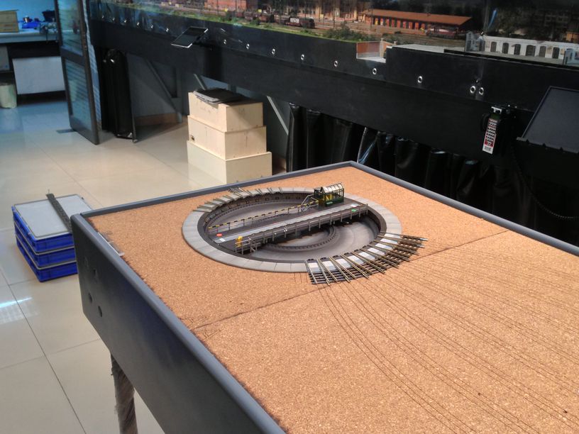
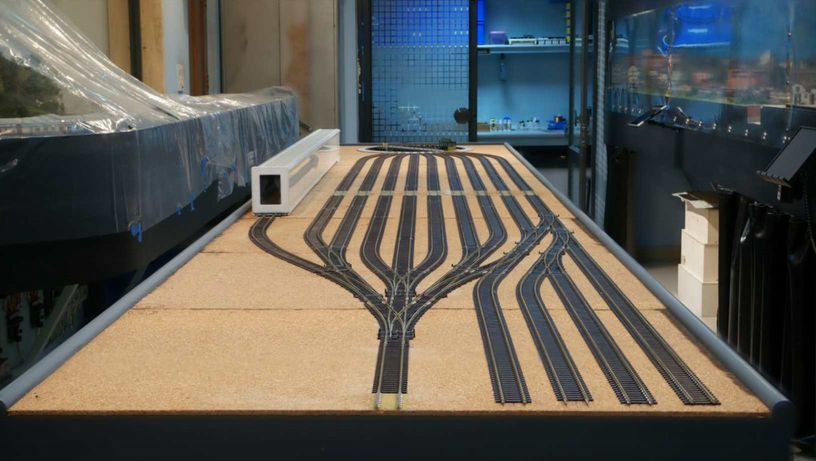
I then turned my attention to the installation of the Fleischmann turntable ….
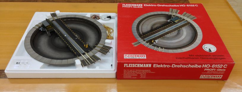
Basically all i had to do was put it into the hole and secure it with a few track nails it was installed !!!
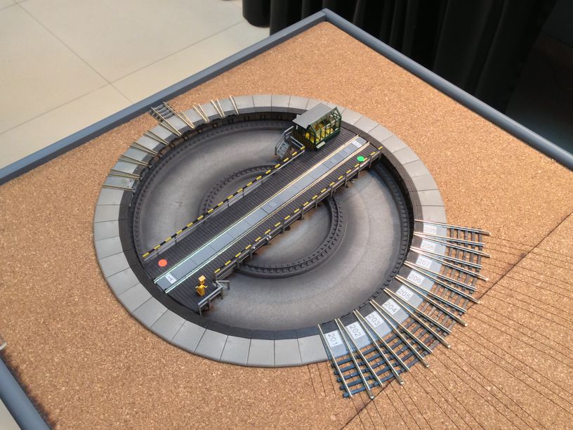
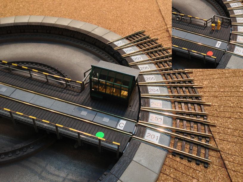
i stuck on some numbers on the tracks from 201 thru 209 and marked T and C with red and green dots. In a later post we will see how these help in the automatic route control of the staging yard and the turntable.
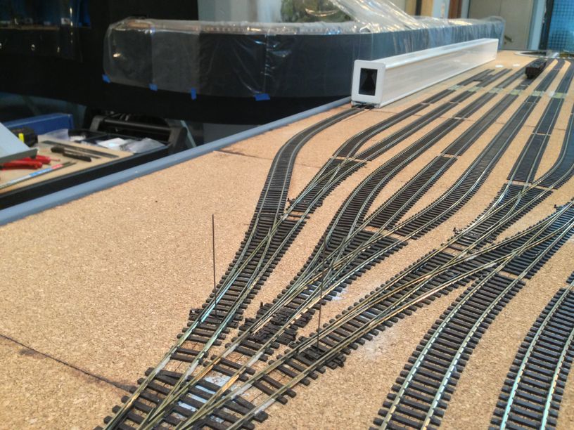
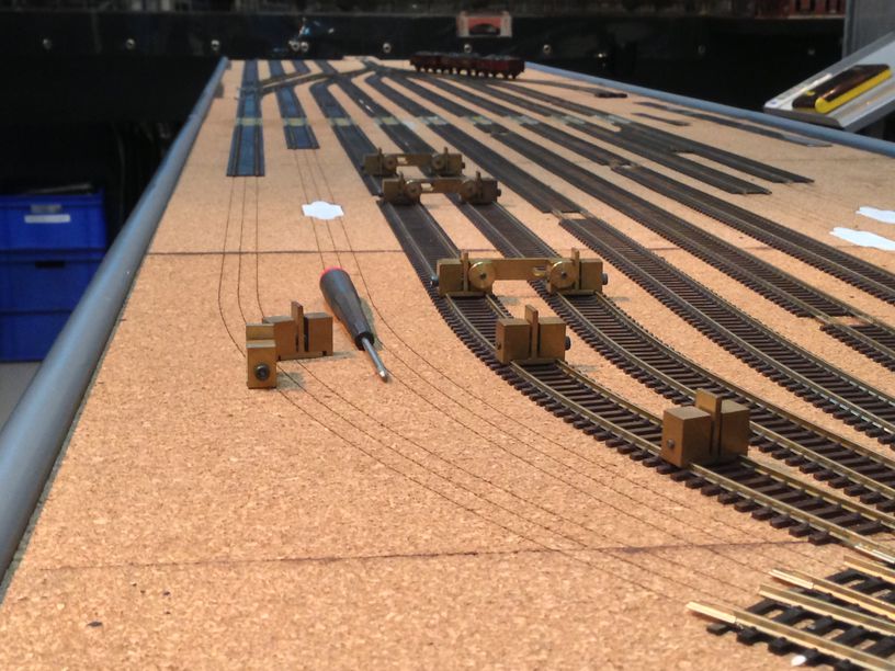
once the turntable was in place all the remained was to bring the rest of the tracks from the module joint onwards to the turntable and connect them to the exit tracks ….
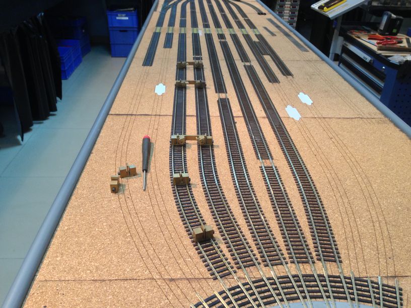
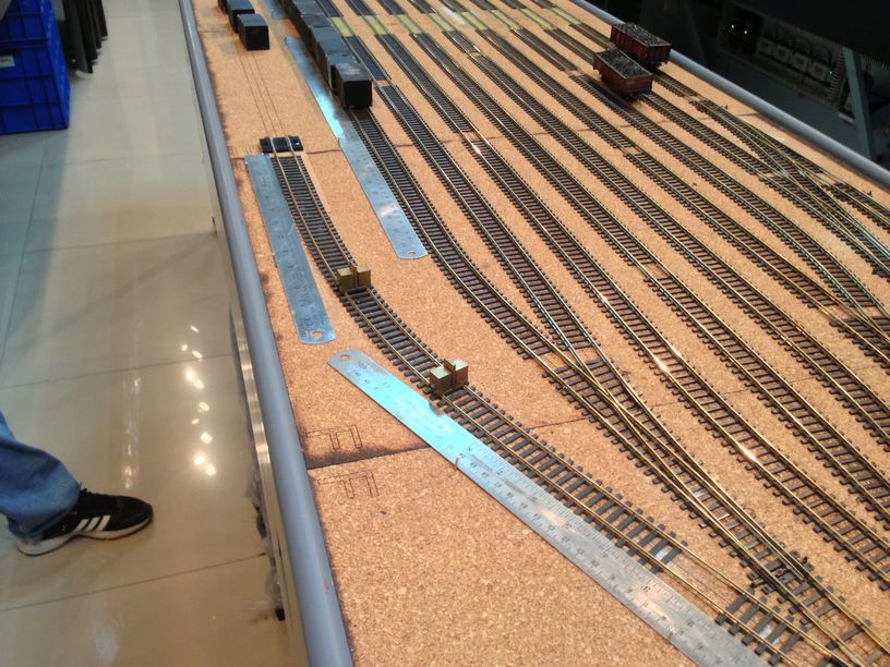
as seen in the pic above , another helpful product was the parallel track tool and flex track clamps from Fohrmann werkzeuge , Germany ….
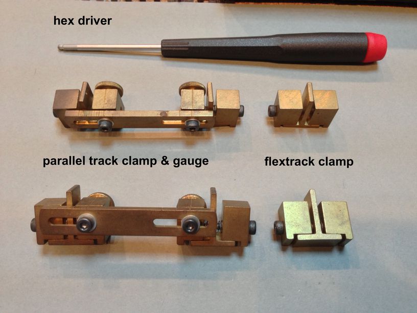
they are basically brass clamps which one can fit on to the flextrack and tighten down with the hex driver. While laying flextrack, one wants to adjust and feel around till the track is in the exact location. The clamps then prevent the flextrack from moving around while one can reach out for glue or nails or whatever tools are needed next …..or even set up alignment for nearby tracks. The parallel clamps help gauge the correct distance between tracks in a yard or group of evenly spaced tracks …..
while laying track i also smear the joiners with flux ……
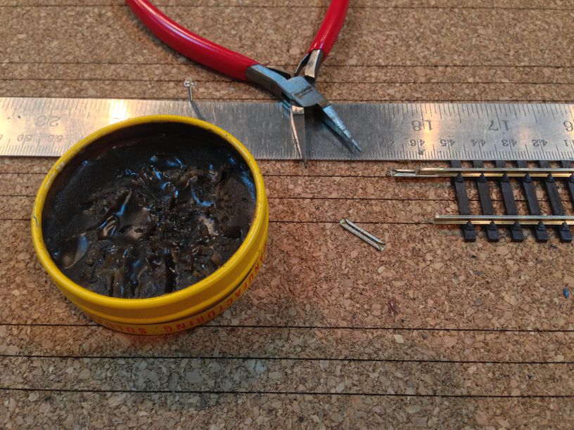
and when i bring the track ends together it oozes out of the joints ….
i do this because later on in the wiring stage i will solder the joints together and if flux is already deep in the joints then the solder will flow into it nicely and give me a solid solder joint …….
once all the track is down , the gaps between the ties need to be filled in …..
this is done by filing down the heights of various cut off or discarded ties so that they can slide easily below the rails and joiners …..
and once the glue dries out , one can hardly tell the difference …..
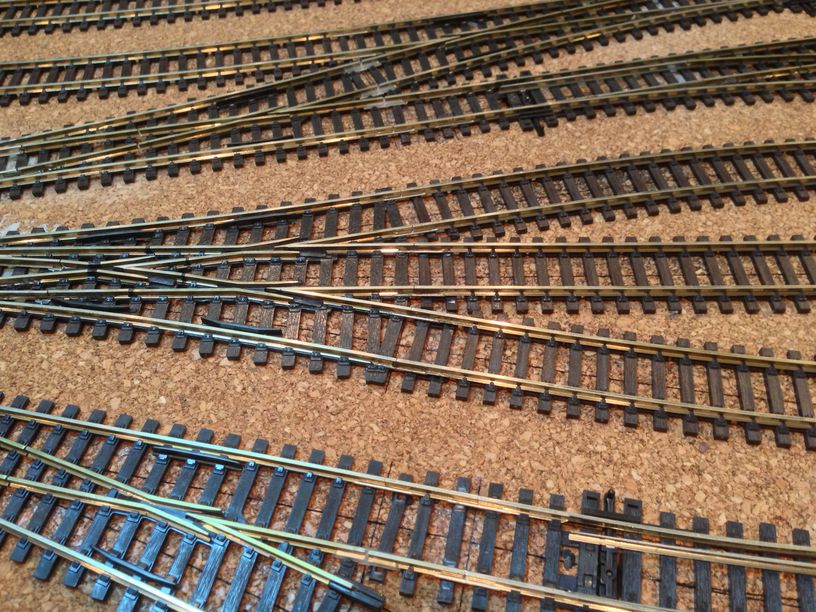
finally all the track is down ……..
 click here for larger pic…
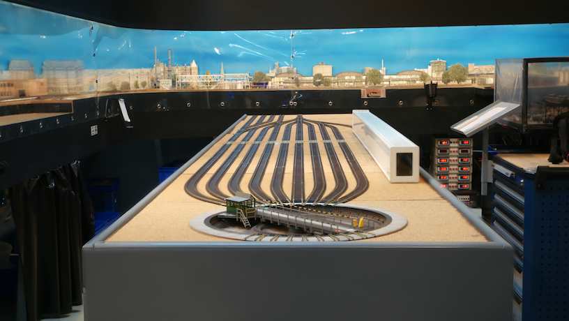 click here for larger pic


previous in the series –points and tortoises install
Hello Vikas,
I am heartily impressed by your use of these milled PCB tie plates! I have never seen or heard of them before but I am going to give them a try on my next project.
I take it they have been installed and in use for a while now, with no problems?
Many thanks for the heads up on these!
Cheers,
John E.
hi Arved
yes , i have been thinking about how to protect the rail ends from accidental damage and i will probably do something similar to what you propose …. right now i am witing up the moules and after all tests are over i will probably adress this issue… vikas
Nice solution. How about using a piece of angle over the edges of the rail to protect them during transport? I had a drop down segment on the layout my father built for me as a child. It was a segment of a double track wye. When the drop down was down so you could enter the control area without ducking under, the rails were very sharp, and would be wrenched out of position when snagged by my trousers. Father would be very upset with me if I did it, and apologetic if a visitor snagged his trousers.
We would just straighten the rail and respike it. Eventually, I learned to do it myself before my father would find the damage, but it was always a lot of tedious work.
I like the trainsafe cassette idea! First I’ve seen it.
Good luck with your module and your blog!
hi chris
good to hear that the pcbs have served you well . I hope that turns out for me as well or i am up shit creek without a paddle !!!
cheers
vikas
Vikas,
I have to put in my input as a long time user of PCB milled tie plates. I have been using these since 1999 and have installed quite a few on modules since that period. I personally have never had a pad become delaminated from the PCB.
In fact in one extreme case, the rail bent sideways at the web of the rail. The joint that was soldered to the foot of the rail contacting the PCB tie plate wasn’t affected.
If for some reason you experience a delaminated PCB pad, clearly more force was placed on that joint then should be asserted on a module in the first place. Perhaps a different transportation solution should then be considered for longevity of the module. Certainly extreme forces could have dire effects over the long term to the structural integrity. However, I think too much emphasis is placed into overbuilding modules for worry of some outlandish force placed onto the structure of the module that almost never happens. Typical placing into a vehicle and setting up will never yield these extreme scenarios.
If you encounter them often, certainly you will have bigger problems then the rail staying fastened to the end. I think you will pleased to see these as a very long term permanent solution. Our group has pretty much standardized upon them forward.
Chris Palomarez
free-mo.org
Hi Tim,
what u mention above has been on the back of my mind – what if the rail got snagged and ripped off along with the copper ( nickle silver??)part of the pc board .
I guess the only choice left at that point wud be to insert a brass screw and solder the track or then an open heart surgery to install a new plate !!!
Knowing my nature of getting an install perfect , i wud probably not be to averse to remove 6 inches of track and redo the whole thing .
I have used and advocated the brass screw method in the past but since it was a new product and i liked the look of it i gave it a shot….
…… having said that i tried prying up the rail on a test mockup and i exerted a lot of pressure but could not rip it off the plate . i think i will do a proper stress test on it and see at what force the rails rip off
i have not put it into any field test yet as i guess that is a while away till the other modules get ready but so far so good. installation was easy , there is no noticeable ” click” when anything passes over the gaps ……. but keeping the above concerns in mind i will hold my breath for a while …..
cheers
vikas
Hi Vikas,
Good to see you are back online and working on a layout!
The PC board endplates you are using is a product we are very often asked to produce. I have always been quite hesitant to make them though. While they appear to work great, and from your images it looks like they have quite a complete system worked out, my concern has always been what happens if the rail gets tore from the boards. If someone catches the end of the rail the copper foil will be ripped from the fiberglass substrate. Repairing this is almost impossible. The only way it can be done is to dig out the old endplate and replace it, which is no small task. I have long advised modelers who ask these of us to use the flat head screw method instead. Should it rail get caught on something and broken from the screw head, it can simply be re-soldered in place.
Keep in mind this is just an opinion and I have not worked with the PC board versions at all, but I can’t help but think it would be troublesome should they get damaged.
What has been your observations so far using them?
Cheers!
Tim Warris
Fast Tracks
hI paul
good to hear from you , its been a while….
i am glad you like the construction process , soon i will be wiring it up and that should be interesting also..
cheers
vikas
Dear Vikas,
I like the way you are building your staging yard. Very tidy, very clean.
Keep up the good work!
Paul Hartman
President FREMO
Extremely industrialized, as usual – very well done! I really like how neat your new installations look. I got a glimpse of the finished part of the layout in some photos, looking forward to seeing them up close.
hi Tobi
yes , you are right in saying that the crude screw heads are not justification enough . I also used a similar method as you described with the cut off brass screw heads . they also completely disappear when the track is ballasted . But i guess the BNM tieplates are a step forward from that and i quite enjoyed installing them , it was easy to do and neat as well…… time and use will tell if it was also the right decision !!!
cheers
vikas
Hi Vikas,
I really like your clean method of fixing track at the module ends. However, your first image of the crude screw heads should not be seen as a justification. This is just a very bad example, which is NOT a common sight at Fremo meetings!
My own method is to first lay the track all the way to the end and glue it down well (except for the last sleeper). I then remove the rails and drill holes between the last sleeper and the sleeper before this, right underneath the former rail. I remove the last sleeper, insert 3x15mm brass screws into the holes, leaving them sticking out approximately 4mm. I cut off the heads 2.4mm above the track bed, thus leaving a brass stump in place. This is filed down to barely clear the rail, which is then quickly soldered to the brass stump. I then replace the last sleeper.
This method leaves a strong connection which is completely invisible. There’s no crude screw head thanks to the 2mm diameter brass stump, which vanishes underneath the rail.
Tobi